Woodworking In America, Contest Winner(s) and Other Stuff…

___________________________________________________________________________________________________

“I am a success today because I had a friend who believed in me and I didn’t have the heart to let him down…”
— Abraham Lincoln

___________________________________________________________________________________________________ 


Hard to believe, but the Pasadena version of Woodworking in America begins on Friday. Can’t wait to put the Dream Team to work… We will have 5 Jointmaker Pro’s making components for Cooter Ditchman’s Earthquake After Detector..

Here is a view after an earthquake;


You can purchase this freshly made and unbelievably accurate device at WIA for a minimum donation of ten bucks–ALL funds go to the Roger Cliff Memorial Fund which provides need based scholarships for the Marc Adams School of Woodworking.


We will have 5 brand new Jointmaker Pro’s with our new Precision Fence Systems that can be taken home on Saturday at end of show. First come first served is the deal. We are throwing in the stand for…. FREE!


We will also be demonstrating the HP6v2, the DJ-1 and the AS-24v3. Mainly though, we just want to have fun with our customers.


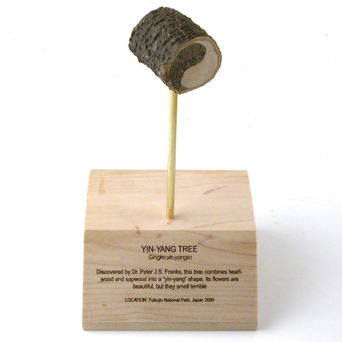
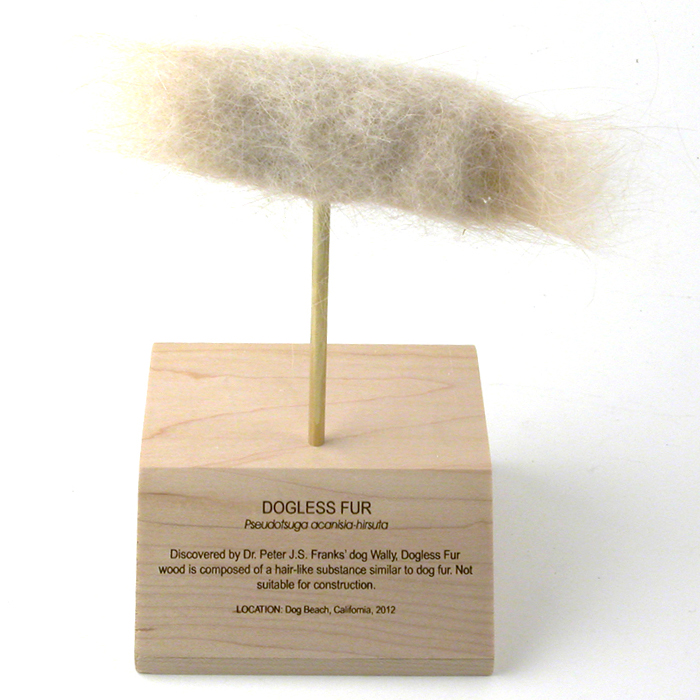
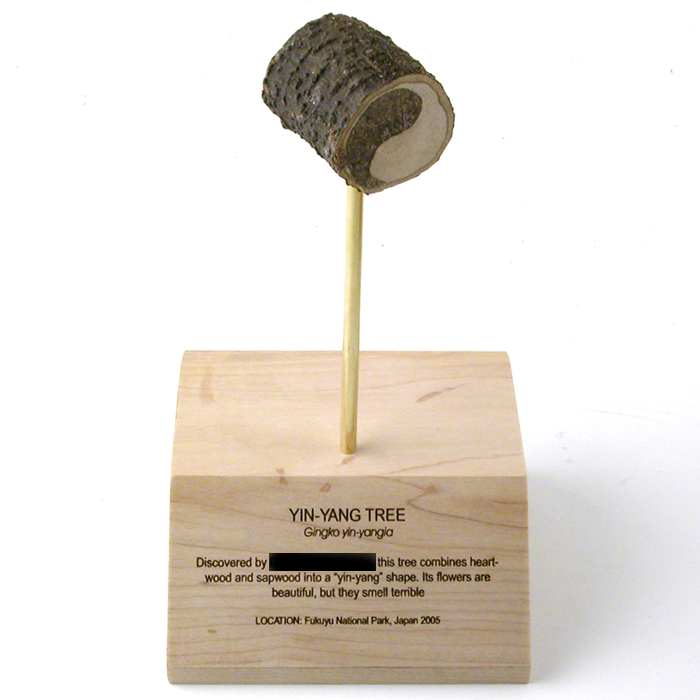
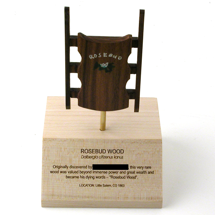
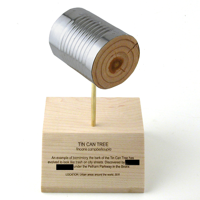
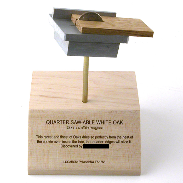
The votes are tallied and here are the winners for the 2012 Rarest Wood in the World contest;
FIRST PLACE (with 33% of all votes)

SECOND PLACE (with 25% of all votes)

THIRD PLACE (with 22% of all votes)


This was a complete sweep by one Dr. Peter Franks. I know it looks rigged but I am from Des Moines, not Chicago.


Congratulations Peter–that is a whopping $850 Gift Certificate coming your way. And due to the overwhelming benevolence of your favorite Tool Potentate, the LOSERS are now WINNERS too–each of you finalists will receive a $50 Gift Certificate for your entries. I really want to do this again next year so put your thinking caps on and let’s create together the Rarest Woods in the World Museum.


I hope to see some of you in Pasadena!


–John

Perfect Tapered Sliding Dovetails in Wood by Hand…Q and A

___________________________________________________________________________________________________

“And in the end, it’s not the years in your life that count. It’s the life in your years.”
— Abraham Lincoln

___________________________________________________________________________________________________ 


Sometime this week we are going to open the pre-order window for our new HP6v2 Tapered Sliding Dovetail System. Thanks to all who commented last week regarding this tool. This has really been a rewarding project–the very thought of making an extraordinarily difficult joint brain-dead easy really excites me.


Because this concept is new, actually foreign might be more descriptive, I thought it would be helpful to answer some of the many questions that we have received (in addition to those unanswered questions on this Totally Awesome and Worthless blog)…in no particular order


Why did you spend time developing this tool?
Tapered sliding dovetails are almost always made with a router, and that is how I made them years ago. I thought the HP6v2 could do the job, and always wondered why the traditional methods left so much to be desired. It is a hard tool to do research on but I did find a little tidbit in The Handplane Book by Garrett Hack where he does not share much love for the Stanley 444. I have never seen this plane up close and personal but the solution seems primitive to me. I don’t know, I just assigned myself the challenge of finding an easy solution–it is an incredibly useful joint that is grossly underused.


Will this system do stopped dovetails?
Yes but it is not obvious. Simply band or add material to the edge where you do not want to see the joint after assembly. This will take a bit of planning but works well.


Can I make dovetails shorter than .300″?
Yes, but you are on your own in making the shims for the soles. Totally doable.


What if I don’t want centered dovetails?
No problem–you just need to figure out your centerlines. This entire system works on centerlines.


Does the joint lock together where I might not need glue?
A 1/2 degree tapered dovetail self-locks and frankly they sometimes are easier to assemble than take apart. So yes it locks.


Can you go through the steps again?–I have read your blog a dozen times and it is still not completely clear how this works to me.
You start by making the male dovetail first as in ALWAYS. There is no debate here. The dovetail sole of the HP-6v2 is fixed to cut a dovetail that is 0.300″ tall. You set the iron to cut about 0.005″ (it cuts from the side, not the bottom) and attach either one or two tapered dovetail guides to your stock with clamps. Next identify the end of your stock that will be at the back (we always slide dovetails from back to front). Next, you will set the fence so the cutter just makes a clean dovetail at the back (the dovetail gets narrower towards the front). The idea (most of the time) is to remove as little material as possible. Cut until the plane quits cutting and repeat on the other side–when completely, your tapered sliding make dovetail will be centered on your stock.


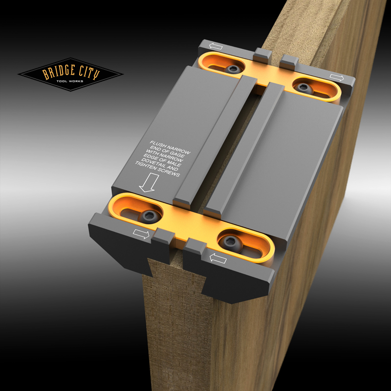
Now we empirically determine the narrow dovetail width using the dovetail gage. This gage needs to be flush with the front of your stock. Lock in place and slide off.


Using a caliper, measure the distance between the flanges on the top of the dovetail gage. This is the width of the groove you need to make for the female dovetail.


Let’s say that width is .582″. At this width you need the 1/2″ dado in the HP-6v2, under .5″ you use the 3/8″ dado kit. (We really do recommend using a second body for this joint to avoid breaking down and resetting the dovetail kit.) Retract the iron, set it in the setup gage and drop the depth fences to the top of the gage and lock all four screws. Next set the iron to cut about 0.002″.


Using our new Adjustable Fence, set the Vernier to 0.00″. Using a square, lock the fence exactly 1″ away from the centerline where you want the female dovetail.


Now here is the really cool part; once the fence is clamped to your stock, adjust the fence 0.041″ (one half of 0.082″–we are only dealing with the material in excess of .5″). And make your first complete plow cut. When complete, adjust the fence to the exact same setting on the other side of zero and make the remaining groove cut. Your 0.582″ wide groove is now complete and centered. How cool is that? You NEVER need to unclamp the fence from your stock.


Take the locked dovetail gage and place the flange into your groove–it should fit perfectly, a nice, no wiggle fit. Make sure it is flush with the front face of your stock and the arrows are aligned correctly indicating that the gage sides are indeed narrow at the front and wide at the back.


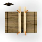
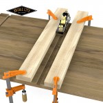
Next, clamp some straight wooden guides to your stock with the edges aligned with both edges of the dovetail guide. This guide knows the “geometry” of the dovetail sole. Once the guides are in place, start cutting until the sides of the plane rub on the guides and quit cutting. That is it. Your joint should go together dead perfect.


John, I don’t like the idea of setting the tapered dovetail guide with that red gage. It looks like a major pain in the ass. Can’t you do better?
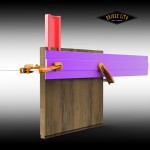
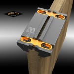
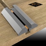
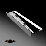
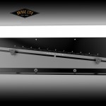
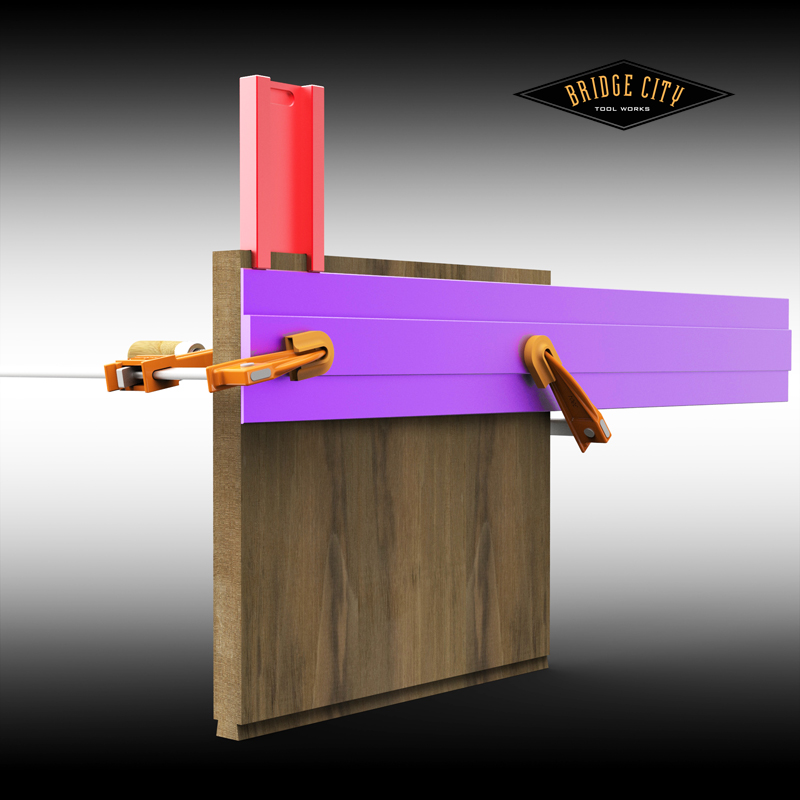
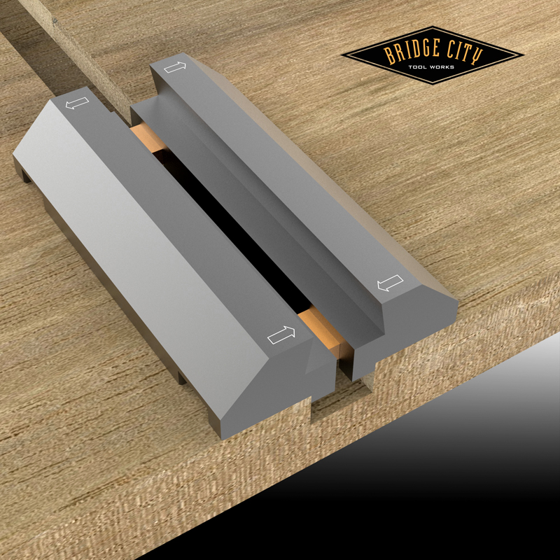
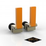
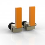
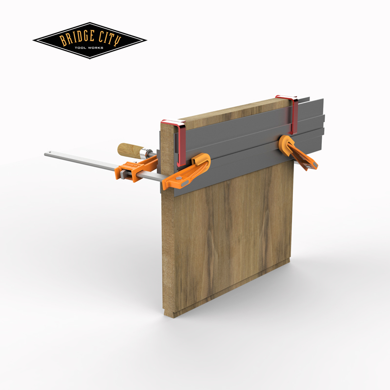
I hear you. Two changes; one we are going to offer the tapered guides in two lengths, 12″ and 24″ so you have a choice. And for those that don’t want to do two clamp ups for a single male dovetail, we have modified the design as below, the little orange hangers will be an accessory for those that want them. Once clamped, slide them off and plane up one side and down the other with two guides clamped in place. And for you picky DSN members, here are the guides in gray… we may go back to purple just to be ornery.
 

I don’t understand the geometry of the iron–care to explain??
First, the dovetail walls are 10 degrees off vertical. The iron is bedded at 55 degrees in the HP-6v2 body. The “V” groove combined with a 15 degree back bevel creates an edge angle of 26.6 degrees, and we do not use a micro-bevel.


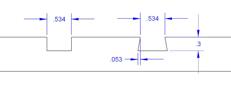
The iron works exactly like a skewed block plane, and in this case, the skew is 35 degrees. Combined with the bed angle of 55 degrees, the actual attack angle of the edge is 40.2 degrees. This is a great compromise for doing the male and female cutting of the joint. Here is an example of how much little material is actually removed to create the dovetail–depending on your material and blade setting, it might take anywhere from 8-15 passes per side, but they are light passes;
 

“Where do the shavings go?
Think of the HP-6v2 Dovetail Kit as a block plane on it’s side. The front throat is adjustable and shavings exit the other side which has been relieved for that purpose.


“How long will that little scoring cutter last?
I don’t know–depends on the material and frequency of use. It does not spin, so when it gets dull, rotate it about a 10 degrees.


“Will the tapered sliding dovetail kit fit the old brass body?
No.


“What can go wrong using this system?
From a math perspective, and as long as our components are in tolerance, any error will be user error.


“Will spare irons be available?
I tried my hardest to make this a dual iron but it didn’t work out. Now, this may come across as blatant hucksterism, but this is one kit where we actually recommend a spare iron. There I said it.


Thanks for the questions! If you have more let us know and I will update this post. Lastly, we are really excited about this plane kit. Literally one of the most difficult joints to do by hand is now almost as easy as a rabbet joint. The secret is this little iron, which by the way, now will allow us to design a kit for making “T” slots in wood. 🙂


–John

Perfect Tapered Sliding Dovetails in Wood… by Hand–Part II

___________________________________________________________________________________________________

“Without tradition, art is a flock of sheep without a shepherd. Without innovation, it is a corpse.”
— Winston Churchill

___________________________________________________________________________________________________ 


Early this week I posted images of our way to make perfect sliding dovetails by hand. And I do emphasize perfect.


Sliding dovetails have an enormous upside and traditionally have been possible primarily using the powered router. Our approach uses the versatile HP-6 Mini-Multi Plane. Making the male dovetail has never been that hard, although adding a taper complicates things.


The tapered female is a beast by hand, and I venture to say the vast majority of woodworkers have never made this joint by hand. Now it is easy–we use the HP-6v2 dado kits to remove the bulk of the channel and then come back using the exact same settings that we used to cut the male dovetail to cut the female–with this system, we ALWAYS cut the male dovetail first. (If you have two HP-6v2 bodies which of course we recommend…you can do this without breaking stride.)


In order to maximize the efficiency of the 10 degree beveled cuts (by removing as little material as possible), the initial dado cut should be as wide as possible. To do this you need a way to determine the EXACT width of your tapered male dovetail and our new dovetail gage does this in spades. This is really cool.


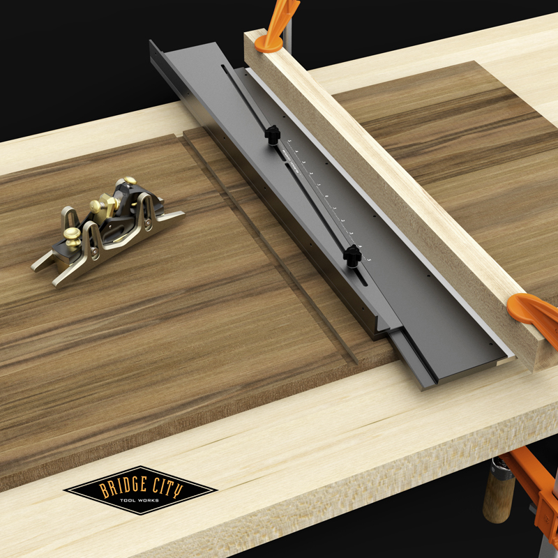
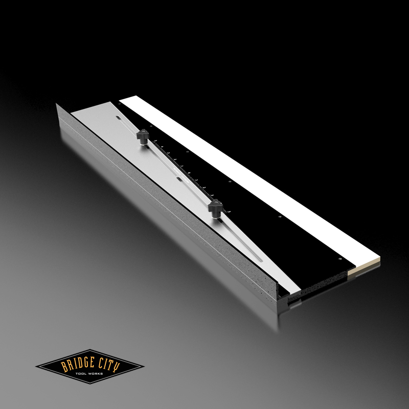
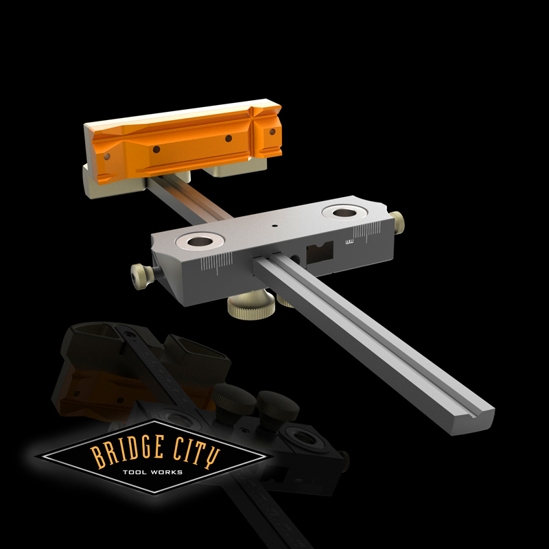
All that said, when you work using centerlines as your anchor, stock width variations can cause havoc. We needed a way to precisely make variable width dado cuts using a fixed width cutter (in this case either 3/8″ or 1/2″). Hence the AF-26 Adjustable Fence was born.


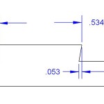
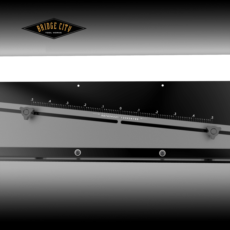
The AF-26 is, 26″ in length and is adjustable in 0.001″ increments up to .5″ either side of zero, for a total adjustable range of 1″.


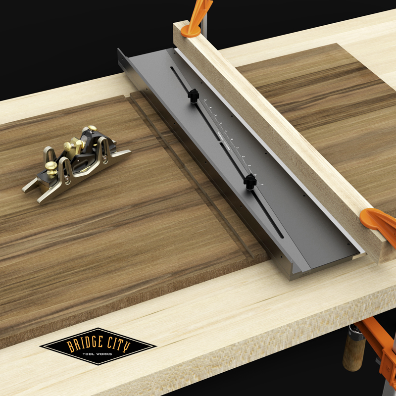
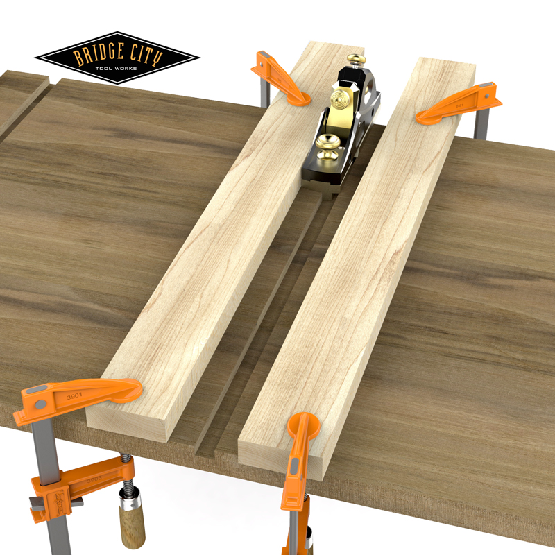
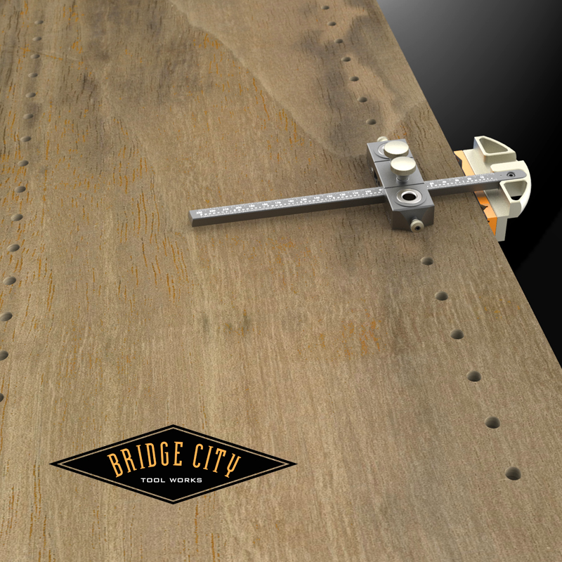
Pictured below is a routine setup to cut the initial dado cut clamped with a caul to a workbench.


Loosen the two lock knobs and the reference face can be adjusted in either direction as seen below;


These adjustments are fast, accurate and fun. More important, you can come back to wherever you were if need be. I wish I would have had this device 40 years ago–tap,nudge, tap back… what a time waste. The tapered, sliding joint is smooth and solid. Did I mention how FAST this is?


The aluminum base fence is drilled so you can attach your own wood fence which will make this tool useful on router tables, band saws, free hand powered routing applications and many more situations where repeatablity and accuracy are required.


Lastly, there are many misinformed folks out there proclaiming that working to tight tolerances in wood is a waste of time, and I would like to believe they are talking about house framing. Without tight tolerances the tapered sliding dovetail does not exist.


The comments so far–as always–are welcome and insightful. Keep up the good work!


–John

Perfect Tapered Sliding Dovetails in Wood…BY HAND.

___________________________________________________________________________________________________

“Time is the greatest thief in life. — Kazeronnie Mak

___________________________________________________________________________________________________ 


Off and on for the past couple of years I have been chasing a way to cut tapered dovetails with our HP6v2 Mini Multi Plane. For the uninitiated, a tapered sliding dovetail just may be one of the most difficult joints in woodworking when attempted by hand.


CAVEAT: I have made thirty or so tapered dovetails in my past furniture making life and none were by hand–all router work. That said, in order for this joint to perform as intended, regardless how it is made, the accuracy required can be daunting.


During the research phase of this project I came across some old “dovetail” planes and none of them work the way we are going to show you. Furthermore, you will find few who claim these planes work well at all. All of the planes mentioned cut a dovetail with the stock horizontal to make the male, and the female dovetail? Well, since I never made one by hand, it appears the shoulders are cut with a saw and then the waste removed with either a router plane or a shoulder plane. I wanted one plane to do both. And in order to accomplish that, we had to invent a new way to make a plane iron.


In addition to the iron, we addressed this project from a series of constraints which include;


1) The male dovetail, regardless of overall width, will always be .300″ tall.
2) The longest female dovetail made with our system is just over 20″
3) We will use either the 3/8″ or 1/2″ wide dado kits for the HP6v2 to remove the bulk of the waste.
4) The included taper will always be 1/2 of a degree
5) Joint layout will always involve the centerlines of the male and the female without fretting about stock thickness.
6) The tapered male dovetail will always be made first.


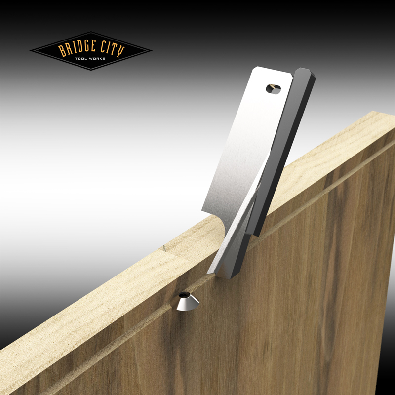
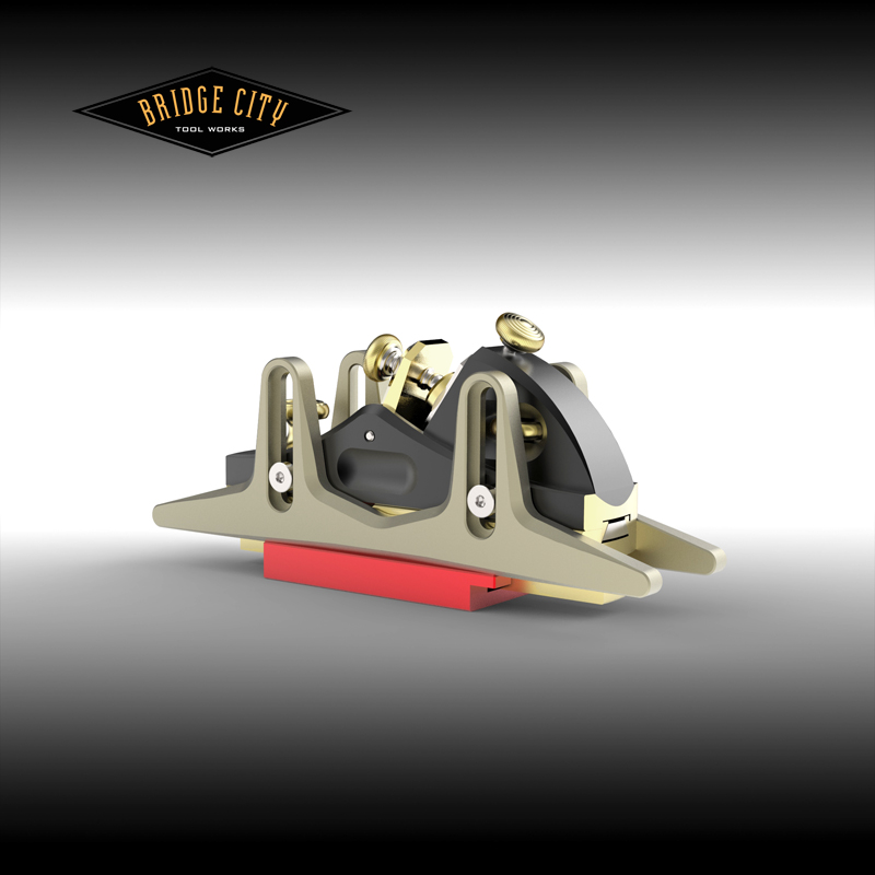
It is the nature of sliding dovetails that you rarely, if ever, cut with the grain. The male is a cross grain cut, and the female is not only across the grain but is primarily an end grain cut. We needed a new way to make a dovetail iron and the results are illustrated below (without the body or fences for clarity), a circular scoring cutter makes the end grain slice and the iron shear cuts the taper (FYI: the bottom of the iron never cuts);


Sharpening this iron is ridiculously easy–hone the “V” groove on the corner of your sharpening stone. Lateral adjustments are made possible by a tapered wedge (pictured below) that uses the side of the plane body as an anchor–up and down movements will move the iron left or right. In practice, we like the iron set to take a cut in the 0.002-005″ range. Because the cuts are light, multiple passes are easy.


The depth of the male dovetail is fixed at 0.300″. To cut the taper, we are making a “left and right” aluminum guide that has a 1/4 degree taper–the combined cuts make a 1/2 degree tapered dovetail. In the image below you see this guide being set up with a depth gage–this is important to prevent a compound cut. In addition, you will always “flush” the edge of your guide with your stock to keep the dovetail centered on the stock. (You can still make off center dovetails if you choose).


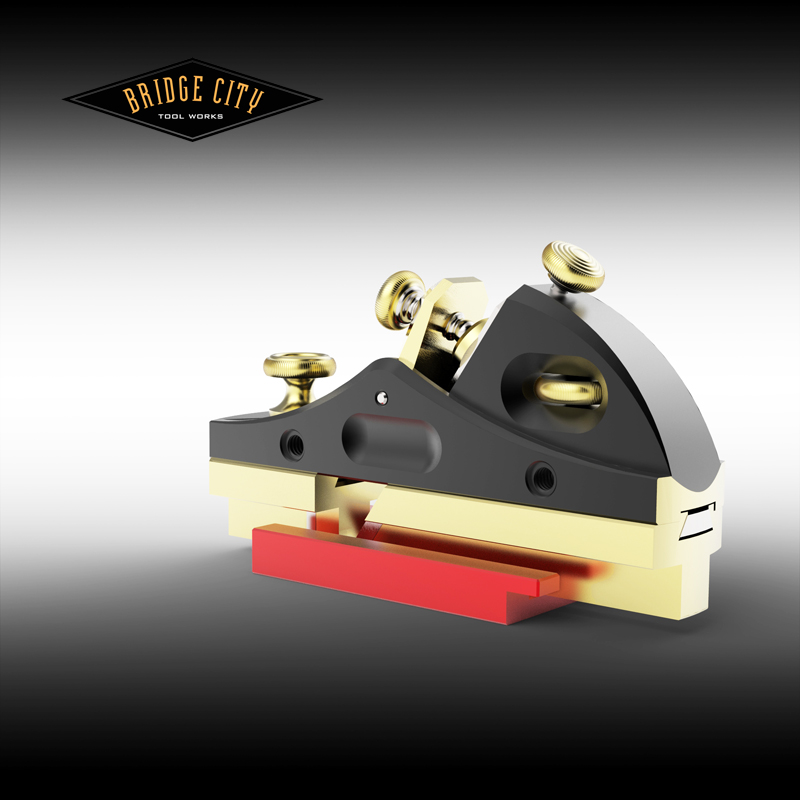
Once the fence of HP6v2 is all set to remove as little as possible material at the widest point of the dovetail (we really like anti-friction tape on the fence face!), it looks like this :


As long as the tapered guide is set flush to the edge of the narrow end of the dovetail for both cuts, your male dovetail will be perfectly centered. You make as many passes until it no longer cuts and repeat on the opposite face–use backing boards to prevent blowout on the exit cuts if important.


The heart of our system to create flawless and perfect sliding tapered dovetails is the dovetail gage. This device literally measures the tapered dovetail width at the narrowest end. The vertical flanges on top of the gage represent the ideal dado width and can be measured with a dial or digital caliper. This will require the bare minimum of wood removal to create the female dovetail. Again, this tool needs to be flush set the the same edge.


As mentioned earlier, you can use either the 3/8″ or 1/2″ dado kits for the HP6v2. We are using the 1/2″ here and the first order of business is to retract the blade and set the tool in the depth gage as pictured below (there is a relief cut in this gage so you don’t have to retract the nicker);


Now we can attach the new depth fences to the HP6v2 so they rest perfectly on the top of the depth gage;


Your next step is to layout centerlines for the female dovetails and then set up shop made guide fences 1″ away and parallel to a centerline. For this illustration, the flanges on the dovetail gage measured exactly .5″ (this will NEVER happen, but bear with me…). Once the dados are cut, flip the dovetail gage upside down and into the dado making sure the narrow end is where you want the narrow end of the female dovetail as indicated by the arrows.


Our project looks like this;


The outside edges of the dovetail gage are each tapered 1/4″ of a degree. We will now use these edges as a guide for out reference edges;


With the dovetail gage removed (lift up or slide backwards) the female dovetail can be cut–up one side and down the other using the EXACT same setting used to cut the male.


The results will be dead on. Now back to the dado width… each and every dado you will need to cut will likely be different because of stock thickness variations. Which is why we will offer the coolest adjustable fence that will allow you to dial in any dado width you need…


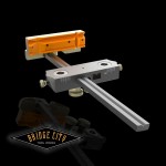
The white strip on the outside edge is MDF so you don’t have to bugger up the aluminum clamping to your stock. Once clamped, you can adjust the width in 0.001″ increments using the built in Vernier;


This adjustable fence has lots of uses in the shop other than sliding dovetails–it is darn cool. Let’s say your dovetail gage indicates you need a dado that is .524″ wide. Set the Vernier to zero, lock the fence down 1″ away from the centerline. Now adjust fence 0.012″ and make your first plow cut. When complete, adjust the fence back to zero and then another 0.012″ for the final pass. Viola! …524″ dado.


Remember when we set the dado depth fences with the blade retracted? To make the dado you will need to advance the blade 0.002-0.004″ which will make the female ever so slightly deeper than the male–this is a big deal so those flat surfaces do not interfere with each other–your shoulders will suck in tight. So there you have it…


I am betting very few (or maybe zero) of the Drivel Starved Nation have ever made a perfect tapered sliding dovetail by hand. Now you all can–how cool is that? Let the dialog begin!


–John

Off Topic: My e-Bike Conversion…

___________________________________________________________________________________________________

“As a kid I had a dream – I wanted to own my own bicycle. When I got the bike I must have been the happiest boy in Liverpool, maybe the world. I lived for that bike. Most kids left their bike in the backyard at night. Not me. I insisted on taking mine indoors and the first night I even kept it in my bed. — John Lennon

___________________________________________________________________________________________________ 


I live at the bottom of a gully. Yes, I am gully folk and that is where I first met Cooter Ditchman, but I digress…


The hill that funnels cars into my gully is not long at 1320 feet–but my gully life resides 130 feet below the summit.


By comparison, it is nineteen and a half miles from the bottom of Pikes Peak, via the Pikes Peak Highway, to Pikes Peak–a 7,000 feet elevation gain. If my little gully funnel were to extend nineteen and a half miles, the total elevation gain would be 10,140 feet–which makes my little hill 30% steeper. In bicycle parlance, my little hill, (fondly referred to as “Heart Attack Hill”) is a grinder.


Interesting drivel yes/no?


Add in the fact that I am substantially closer to age 70 than I am 50 and you can see why it is problematic to ride my bicycle to work–a short 4.5 miles away. There is no way to warm-up and that is the excuse I have been using for the past 10 years to drive to work. Perhaps more important, there is no shower facility–even though I can remain minty fresh without a shower for weeks…


That said, I am no stranger to cycling having logged over 6,000 miles (on my 1972 Motobecane road bike) in Oregon alone by participating in Cycle Oregon 10 times. In addition I have completed several double centuries (200+ miles in two days)–and yes, your butt hurts like hell afterwards. So it is not that I am a lazy ass, cycling is pure drudgery when you live in a gully.


Last January during my work retreat, I attended a San Diego farmer’s market in the heart of Little Italy and saw my first electric bike. I didn’t know what to think at the time, but it made an impression.


In June, I read a magazine article explaining why all of the major car manufacturers were getting into the e-Bike business–in short, it is perceived as a serious threat to commuting by car. This interested me enough to start researching e-bikes.


Lucky for me, Portland is home to the e-Bike Store and I quickly learned there are three main categories of e-bikes, front wheel drive, rear wheel drive and mid-drives. All have their pros and cons and if this interests you, there is plenty of info available on the web.


I chose a kit to convert my old Trek 7600 hybrid into a 500 watt front wheel drive e-bike with the help of the friendly staff at the e-Bike Store. Total damage was $1300–more on this later.


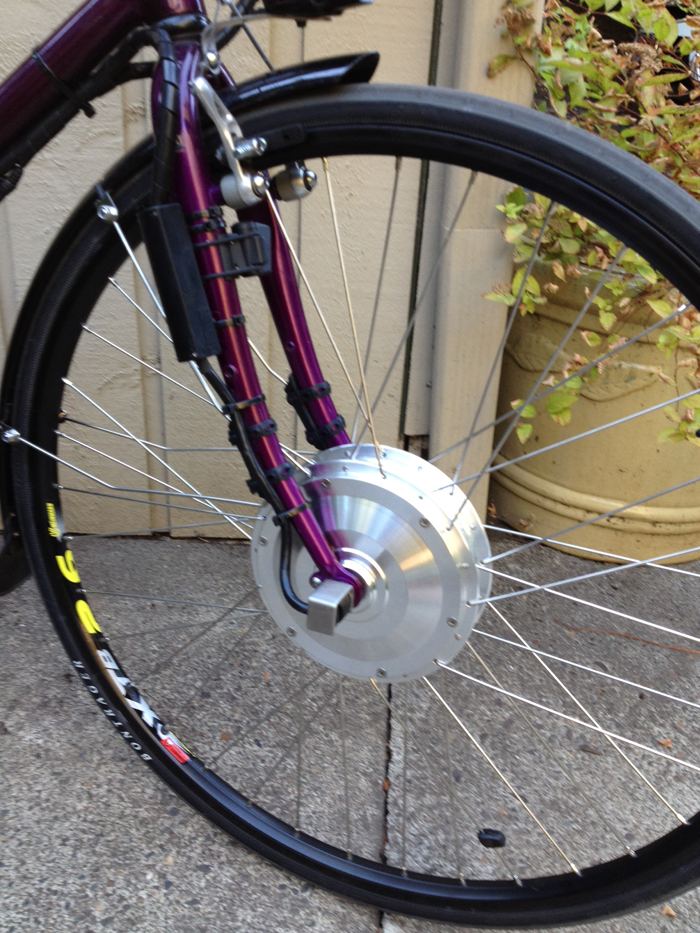
I apologize for the crummy cell phone pics, but the following images help to explain this process. Here is my bike after the conversion, the motor is the front hub, and the 36v battery is locked into the special rack;


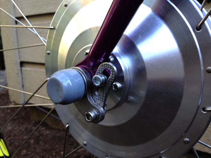
The most important aspect of a conversion is the reinforcement of the front dropout–the torque on these geared front hubs is enough to “lay rubber”. Without this reinforcement, the motor is capable of shearing the dropout–an equal but opposite force that could be seriously dangerous if ignored.


All of the electronics are weatherproof–here you can see the disconnect for the front wheel in the event of a flat…


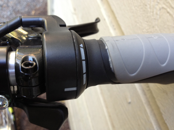
The electronic control is basic–battery level, and the percent pedal assist in 20% increments (the blue lights), here it is set for 60% battery assist when pedaling–no pedaling, no assist… unless you manually override with the motorcycle grip style throttle. Range is 20-30 miles between charges. The battery will go from dead to full in 3.5 hours.


If you just want to zip around at a 20 mph maximum without pedaling, the throttle looks like this;


I have had my new “old” bike for about a month and I am ecstatic with the results. With gas at $4 bucks a gallon it cost me about $1.80 per day for my commute without calculating wear and tear/oil/tires or insurance. Although this is not my motivating reason for the conversion, it adds up fast. In addition, I called my car insurance company and was able to reduce my annual premium by $130. So for those of you who insist on timely payback, the math may work in your favor–I actually did not care, I was more worried about being mistaken for the Michelin man while walking downtown… I needed exercise.


E-bikes are the fastest growing transportation sector in Europe and there are approximately 15 million of them in use. There are 150 million of them in use in China. The last number I saw for the U.S was about 800,000 which makes the e-bike business a nascent business.


Interestingly, the whole topic of e-bikes with friends and family is polarizing. “What is wrong with pedaling?” Or my favorite, “That is cheating!”. “I am a strong rider, so I don’t need that…” Whether these are valid or reactionary, the fact remains that I have been riding my bike to work without the need of a shower. That is awesome.


It wasn’t long ago that mountain bikes were polarizing and as it turned out, they completely rejuvenated the bicycle industry. I believe e-bikes will have a much greater role in changing the way we move ourselves on the planet–it has started seemingly everywhere else but here. Regardless, it is an amazingly fun ride. And consider this; all things considered equal, one rider on an e-bike and one on a regular bike ride until the unassisted rider burns 1000 calories. The e-bike rider will burn 300-400 calories. But get this–at the end of one year, the e-bike rider will burn about 10 times more calories because riding an e-bike is addictive. (When I find the link to this article I will update this post–I can’t find it.) One Portland customer bought an e-bike from the e-Bike store last fall and has lost almost 50 pounds in 8 months.Although my experience is albeit short, I can see why, riding is addictive in a world without hills.


When I last filled my car with gas I had driven 301 miles on that tank. More telling was my average speed for that tank of gas; 23.9 mph. The last 75 miles on my e-Bike my average speed was 15.1 mph. That is amazing to me. I may be getting closer to 70 but I feel like I am pushing 13! I know an e-bike may not be for everybody, but it is a really fun way to get to work and burn a few calories to boot.


One last thing–according to Wake, the proprietor of the e-Bike Store, 95% of the folks who actually come in and ride an e-bike buy one. If I was 50 years younger, I would get in this business in a heartbeat!


–John


PS: My conversion was not fool proof and uncovered a few, but solvable surprises. FYI.

DJ-2 with Dual Heads…

___________________________________________________________________________________________________

“Men, like nails, lose their usefulness when they lose their direction and begin to bend.”
—Walter Savage Landor

___________________________________________________________________________________________________ 


Tuesday we will open the pre-order window for both the DJ-1, DJ-2, Universal Jaws and both Imperial and metric bushing sets. We don’t plan on making these again until the fourth quarter of 2013.


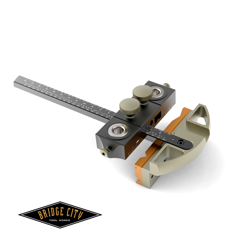
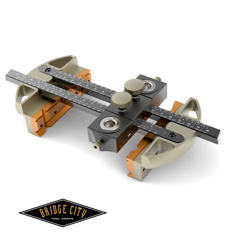
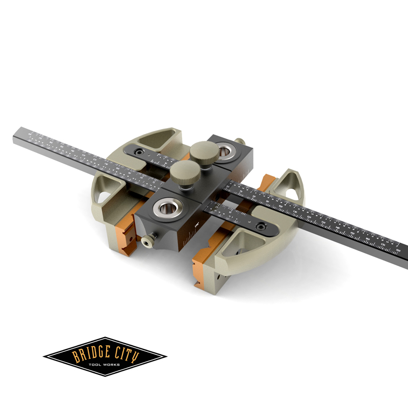
Many thanks to those DSN members who provided feedback–I think the DJ-2 is a great new tool and we are excited to hear how you folks use it in your shops. The two images below illustrate what you can do with a second bushing housing, either in tandem or two completely different jig setups;


Dual heads may not be for everybody, but at least the option now exits.


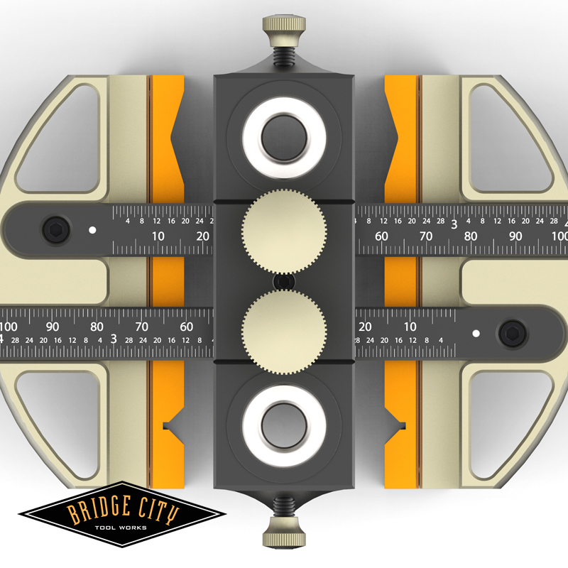
The image below shows how the centering function works–I used the metric scale (way easier) and you can see the spacing is identical on the left and right which indicates the drill line is centered. Your favorite Tool Potentate oriented the graduations so you don’t have to read upside down. Cool yes/no? 🙂


Lastly, for you HP6v2 owners, coming in September, a tapered sliding dovetail kit. BTW, tapered sliding dovetails may be one of the most difficult joints to make in wood. But not for long. Also coming in September is the 2012 “Fab Fifty” tool. Yes, it will be made from stainless steel and that is all I am saying about that!


Again, thanks for the feedback. The fact that Roger Savatteri is happy is a minor miracle!


–John

2012 Rarest Wood in the World Finalists

___________________________________________________________________________________________________

“Creativity is a natural extension of our enthusiasm.” —Earl Nightingale

___________________________________________________________________________________________________ 


First and foremost, this blog is totally awesome and worthless.


That said, our 2012 contest to “discover” the rarest wood in the world is our best contest to date. We are going to do this again so hopefully those DSN (Drivel Starved Nation) members who did not participate this round will get off their glutes and compete.


Thanks to all who participated! Now for the entries in no particular order;


YING YANG WOOD

___________________________________________________________________________________________________ 


ROSEBUD WOOD

___________________________________________________________________________________________________ 


TIN CAN WOOD

___________________________________________________________________________________________________ 


QUARTER SAW-ABLE OAK

___________________________________________________________________________________________________ 


NANO WOOD

___________________________________________________________________________________________________ 


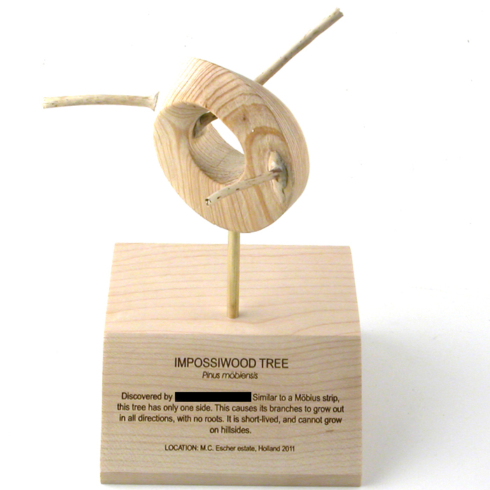
IMPOSSIWOOD

___________________________________________________________________________________________________ 


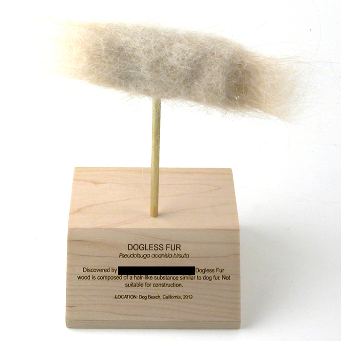
DOGLESS FUR WOOD

___________________________________________________________________________________________________ 


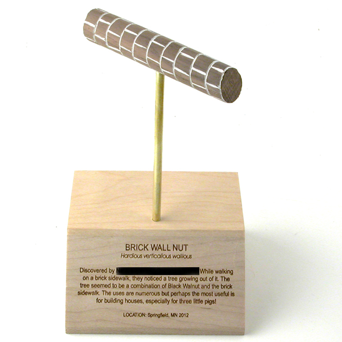
BRICK WALL-NUT WOOD

___________________________________________________________________________________________________ 


BLOB WOOD

___________________________________________________________________________________________________ 


Now it is time to VOTE!


Listed on the left column (towards the top of the post) are our nine finalists. Voting will be open through September 10. Top PRIZE is a $500 BCTW Gift Certificate!


Second and Third Place Prizes depend on how many DJ-2’s we sell… You can vote for your top three favorites. Tell your friends. Tell your enemies.


Tell somebody! And the next time we do this, submit an entry. What part of FREE MONEY and FUN don’t you get?


–John

The DJ-2 Drilling Jig Will Open for Pre-Orders Soon…

___________________________________________________________________________________________________

“Great minds discuss ideas. Average minds discuss events. Small minds discuss people.”
—Eleanor Roosevelt

___________________________________________________________________________________________________ 


Sorry Drivel Starved Nation…still alive?


I took a detour to the beautiful island of Kauai to visit the wettest spot on earth. It seems it was just yesterday that the wettest spot on earth was my bed… or so it seems. My how time flies…


We are finally done addressing the needs of all of our DJ-1 owners who want to easily drill offset holes. Sometime in the next couple of days, the DJ-2 will be released for pre-order.


If you already own the DJ-1 pay close attention to the pictures below, because you will have several options to consider.


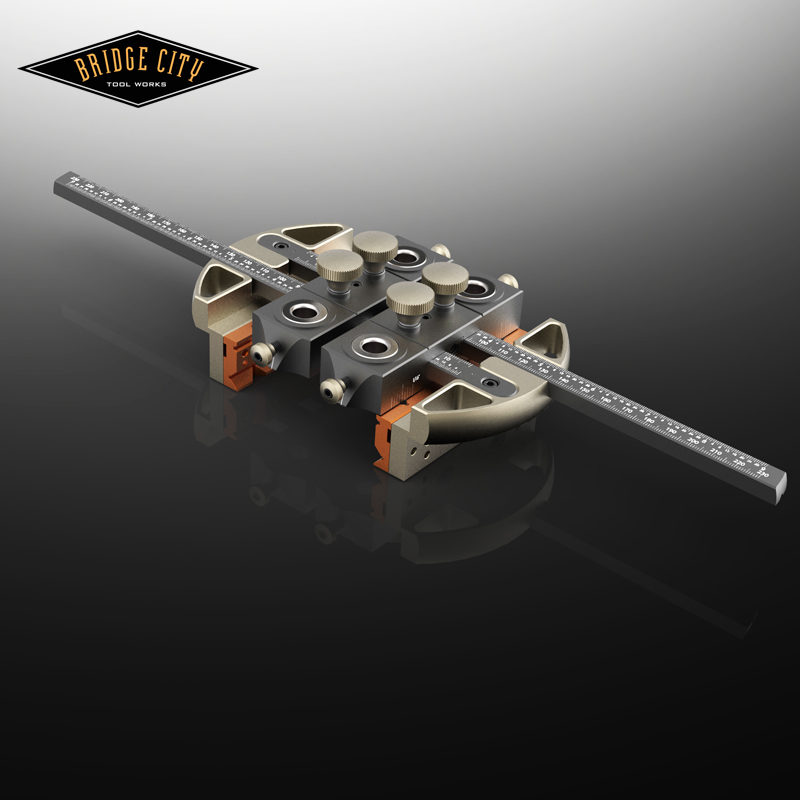
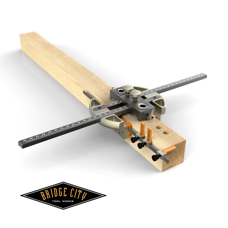
The following image is the DJ-1 with our new stop system;


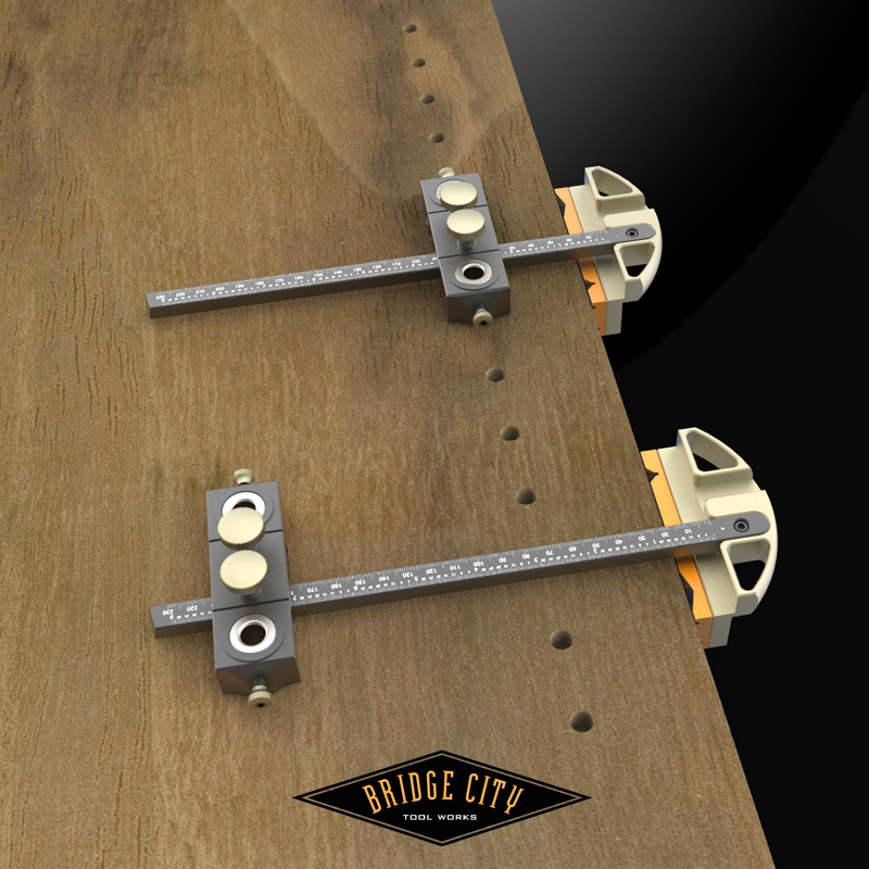
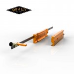
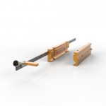
This image illustrates what a three hole drilling sequence would look like using our new flip stop system. These stops can be clamped either on top or the bottom of the stop beam. Regardless of position, the stop arm will flip out of the way. The clamp beam is held in place by two brass set screws in the orange jaws. You will be able to set stops approximately 7 inches from the centerline of the bushing. These stops can be used for any purpose but really shine for drilling the top and bottom holes of mortises in identical parts.


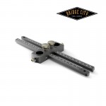
If you are a current DJ-1 Owner and wish to convert your DJ-1 to a DJ-2, the most economical way to do so is to purchase the basic kit pictured below;

All you need to do is remove the two outrigger screws from your DJ-1, and the orange jaws (or Universal Jaws) and attach to the DJ-2 arms which takes about 2 minutes. This will give you the best of our Drillng Jigs.


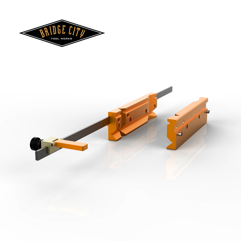
If you would like to add the flip stop system to your DJ-1, or the DJ-2 conversion pictured above, the kit is pictured below;

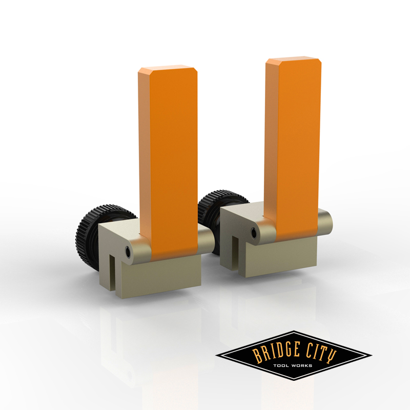
The stop system comes with one flip stop. If you would like additional stops, they will be sold in pairs;


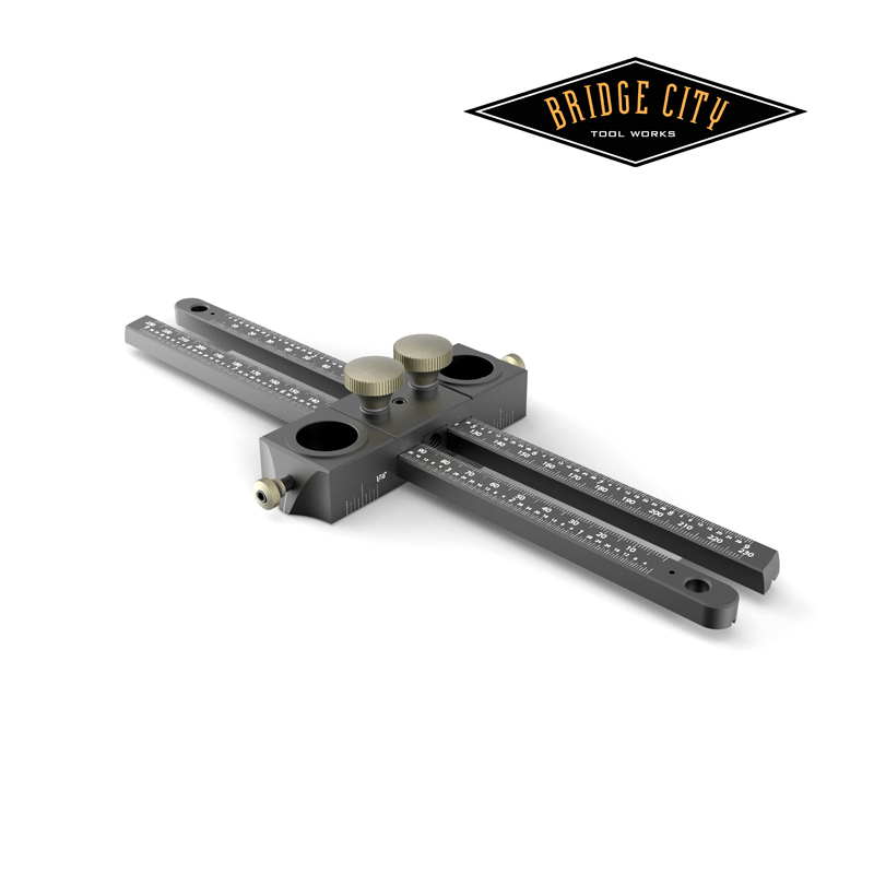
New and noteworthy for the DJ-2, the arms are 2″ longer than the DJ-1, we beefed up the bushing lock screws, and as you can see by the image below, the arms positive wedge lock to the bushing housing;


Drilling hole arrays is as simple as sliding out one outrigger/arm and setting your centerline distance;


Several customers have inquired if they could just purchase a bushing housing and the answer is yes, we will make those available too. As you can see, the 1/4-20 tapped hole in each side will allow you you invent any kind of jig for angled holes you can conjure using your existing bushings.

We are not discontinuing the DJ-1 because the self-centering function is invaluable in certain applications. You can center with the DJ-2, but it involves using the centering rules on the arms. Many thanks to the DSN for contributing to the evolution of this tool.


Lastly, we are just a few months from 2013–our 30th anniversary year. Lots of cool stuff happening, including our book, but one thing is just off the charts huge. I can’t say much at the moment but I can say this; if you ever wanted to visit Portland, the third week in August, 2013 would be a great week. 🙂


–John
DJ-1 Offset Capacity and More…

___________________________________________________________________________________________________

“A perfection of means, and confusion of aims, seems to be our main problem.”
—Albert Einstein

___________________________________________________________________________________________________ 


Yesterday we actually built this version. I can’t speak for Michael, nor would I want to, he disagrees with me too much, but I know he likes this version as much as me.


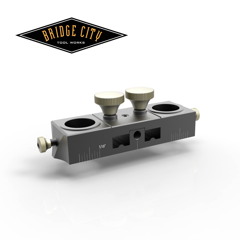
It all starts with a revamped bushing holder–it can be used by itself and we have added tapped holes in the side for what ever contraption you conceive to hold the bushings over a surface.


If you want to drill a hole on a plank (bookshelf holes for example), slide in one arm and set the jaw to your desired center line from the edge using either the imperial or metric rules.


Off center holes are easy, slide in the other arm-the graduations indicate the distance of the jaws from the edges. The bushing housing slides so effortlessly across the beams… so smooth in fact Michael guarantees you will have an uncontrollable desire to call an 800 number that charges by the minute… Did I just say that?


To center drill, I recommend using the metric scale, you are not measuring, you just want the same number on the left as on the right. Your center will be within .005-.01″; it is easy and fast.


The answer to off center drilling was under our noses the entire time. This will work with the Universal Jaws, and our new lock system locks 100%–no give or wiggle anywhere.


I am sending this out for pricing, but in my opinion, this makes the DJ-1xxx a better tool for less cost.


What is not to like?


Thanks for all the cool feedback–especially from the Thursday happy hour bunch…


–John
DJ-1 Offset Holes…Food for Thought/Comments Welcome

___________________________________________________________________________________________________

“Perfection is achieved, not when there is nothing more to add, but when there is nothing left to take away.”
—Antoine de Saint-Exupéry

___________________________________________________________________________________________________ 


For those of you who have been following the idea train regarding an offset hole attachment for the DJ-1, you have seen a couple of ideas pop out of the BCTW skunk works.


I like the micro-adjuster, I like that the latest permutation is sexy, et al.
But I remain unconvinced it is the best idea for drilling off center holes. How about this idea-


Speaking to both DJ-1 owners (and there are many of you) and potential DJ-1 owners, what if we were to build what looks like an identical DJ-1 but the bushing head simply floats on the two beams–we ditch the self-centering aspect?


Current owners already own the bushings and perhaps the Universal Jaws too. This version simply gives you the ability to traverse the head back and forth across the capacity of the tool and drill offset holes to your hearts content.


Personally, I find the nose cursor very useful and have no difficulty aligning centerlines to the nose cursor. We will also be able to add both metric and imperial grads to the top of the arms indicating the centerline difference from the EDGE. Are you listening to your echo David? And get this, if we etch the same rule on each beam, you can center the bushings by using the beams like a centering rule–same reading on the left and right and the bushings are centered, and exactly the same distance from either edge! We very well may be able to both systems on one tool creating one SKU. Metric for centering is easier and preferable in my opinion.


Second, this tool would cost less to make and perhaps broaden the appeal in the market–just thinking out loud here. It would be an elegantly simple solution in the most compact form–and fast. These three criteria appeal to me.


For current owners, we could offer it without the orange jaws, four screws is the difference. All of the pulleys go away, the cable assembly, and requisite slots and tapped holes disappear too-these are not insignificant costs. Our thumb to the wind guess at this point is that this version would cost about the same as the micro-adjust version–maybe less.


We disassembled a DJ-1 and created a working version of this idea and I like it. It will be even better with the grads.


If enough of you chime in, I will mock one up when I get back from my magic class in a week.


–John