Last April I taught two classes at the Marc Adams School of Woodworking on how to make my “Fog of War”, which is a metaphorical sculpture posing as a chess set.
There was not enough time in the week to make both the players and the board and I promised to make this post available for those who wanted to complete the piece. So here ya go!
Although these images are focused on the lattice work, the bones of the board were made exactly the same way, the sticks were bigger (thickness of 0.150″ and a width of 1.375″.)
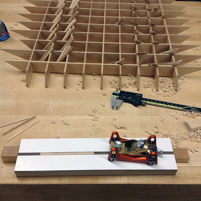
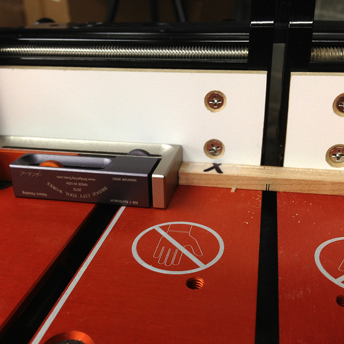
In the image below you can see the simple jig for thickness planing the lattice strips. I used the HP-8 plane with depth skids to dimension the sticks from 0.060″+ to a precise 0.050″. The accuracy of using depth skids is off the charts – all 240 sticks were within 0.001″ of 0.050″ in thickness. As you will see, this accuracy is paramount to making gap free joints. To set the skids to the correct depth, I set the plane body on gage pins, dropped the skids and tightened. I am a big fan of gage pins in woodworking and you will see later that I used them in a couple of applications in this project. I used a similar set-up to dimension the sticks to their exact width of 0.220″ and was able to do 4 at a time.
After all 240 sticks were properly sized, I pre-finished them by dragging all edges over a rag loaded with wax.

Here’s a pile of waxed sticks drying.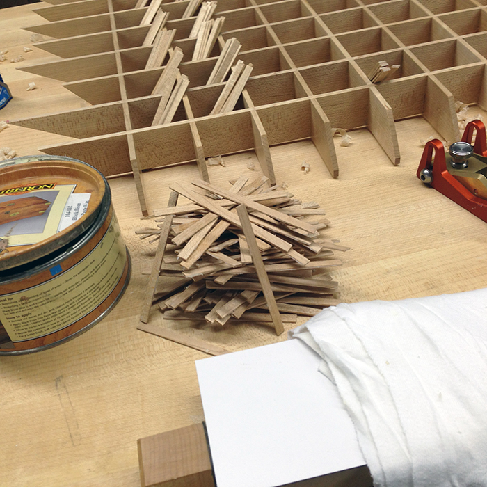
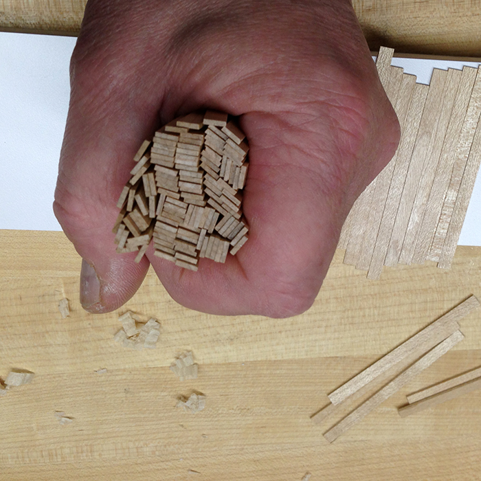
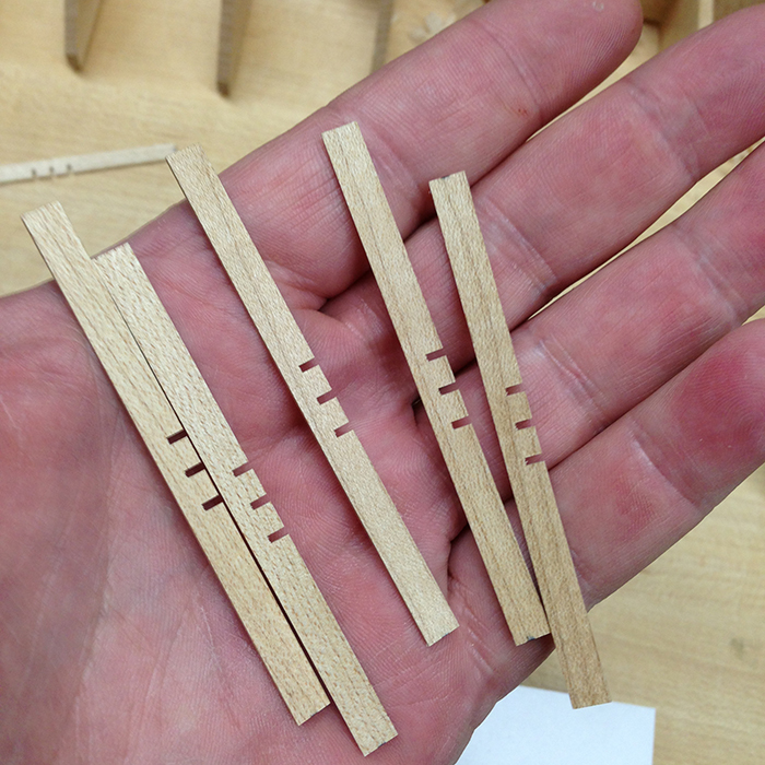
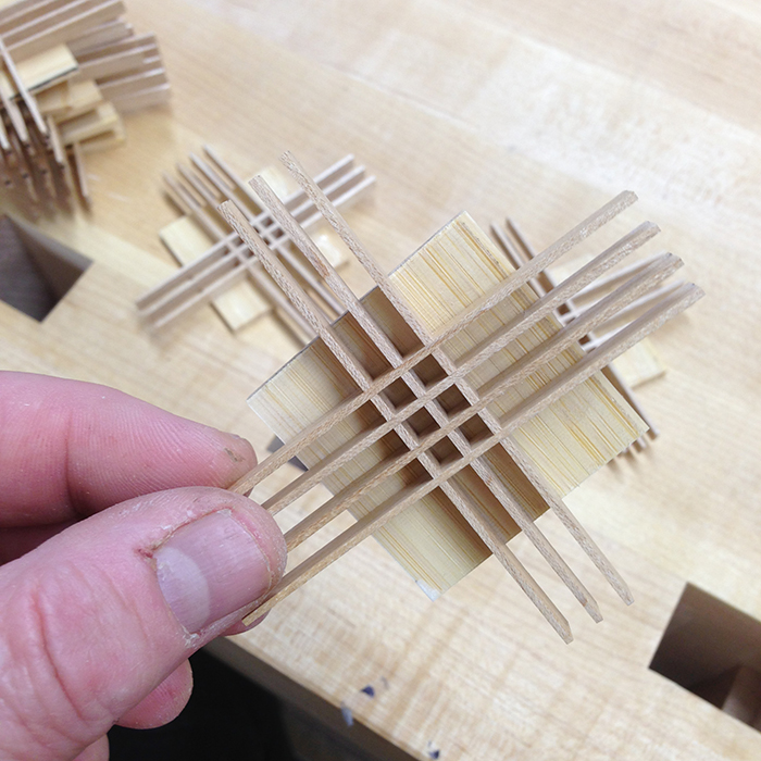
It took a while to buff all of these out by hand, but they were baby butt smooth when done. Here’s a fistful of pieces and you can see the precision that is possible using depth skids…
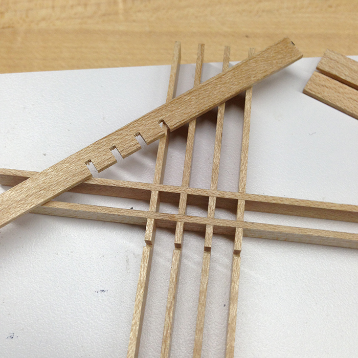
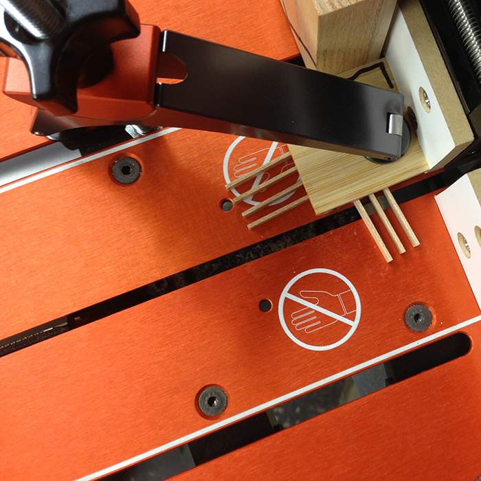
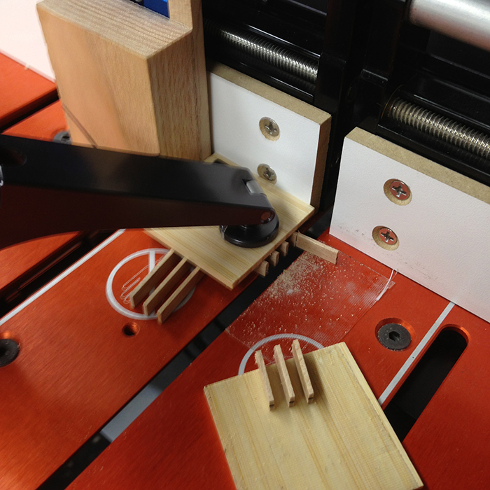
Next, I created bundles to gang cut the half-lap joints using Scotch tape – and trimmed one end for reference using the Jointmaker Pro as you can see here. The cuts were all single pass.
Using the KM-1 Kerfmaker against the JMP Precision Fence the half-laps were cut in 3 passes per joint. I cut one joint in each of the bundles before I made a fence move. I literally could not feel the saw cutting when I made these single pass cuts.
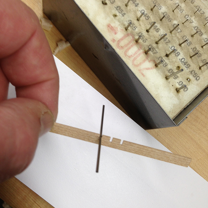
I made a test cut and checked the accuracy using a 0.049″ diameter gage pin which would make for a 0.001″ interference fit between members. Here the gage pin fits perfectly. When you are working at such a small scale, seeing and measuring becomes tedious. It is easy to quantify slots and grooves with gage pins.
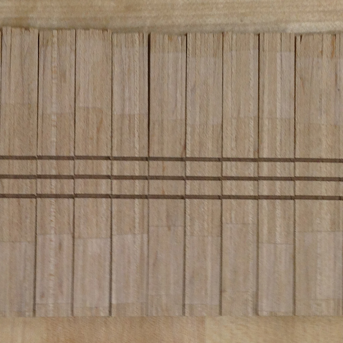
With all the joints cut, it is easy to see the accuracy, and all of this was done by hand. The “grids” of the lattice work were 0.150″ square and the math is straight forward, the fence stop needed to be moved 0.200″ between cuts (the desired opening plus one stick width).
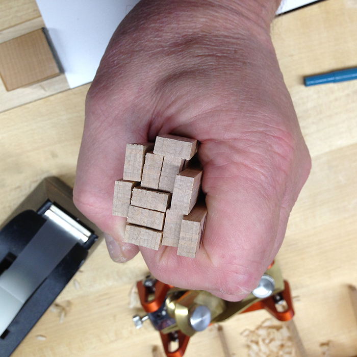
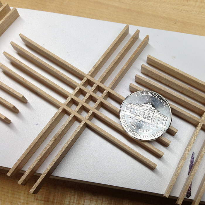
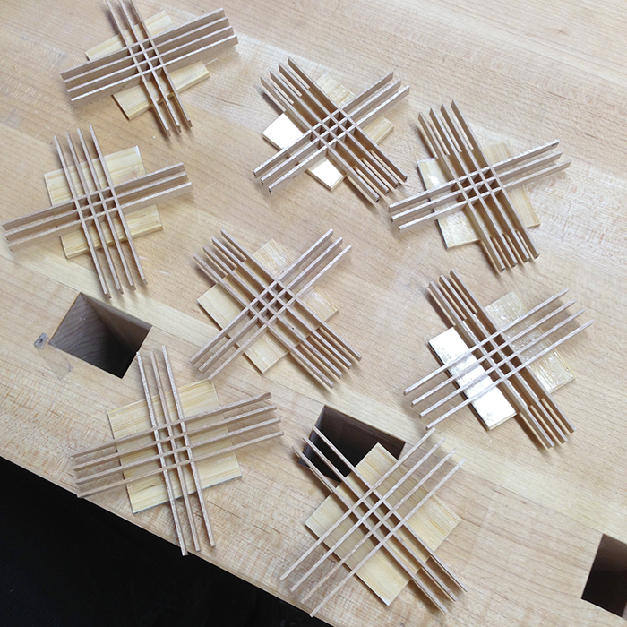
Here’s what the finished and waxed pieces look like when complete…
Now the fun part; assembly. All of these joints went together with just a tiny bit of finger pressure. If your stock width varies, you will either have gaps (anybody can make joints with gaps) OR, if it is too tight, the sticks will yield and curl, or break. All of the precision touted in this post is absolutely necessary. There is no glue used in the grid assemblies.
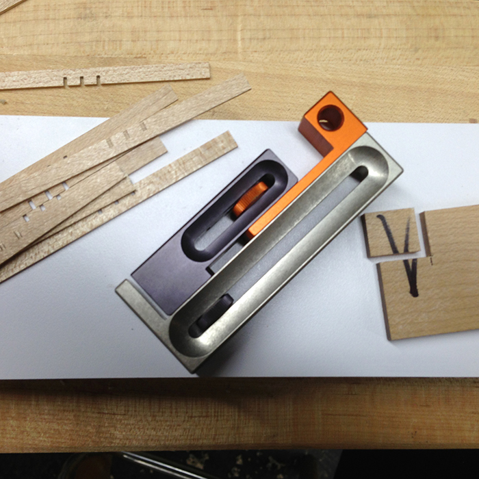
Here you can see the KM-1 and the piece of wood I used to calibrate to the blade in the JMP…
I made this project more stressful than I had planned. I did not make enough extra sticks so I had little room for screw-ups. Unfortunately, I am really good at screwing up..
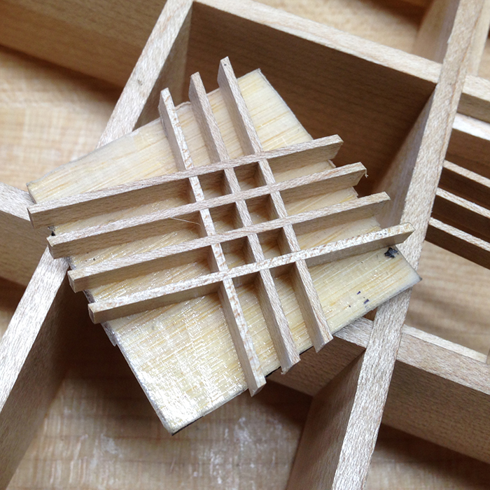
It is now time to cut the lattice to fit the openings in the big board. To be safe, each and every lattice was measured and fitted one at a time. I started by double stick taping a backing board to each grid assembly. This served as a clamp pad and kept the sticks from bending during the four cuts. No two grids are orientated the same.
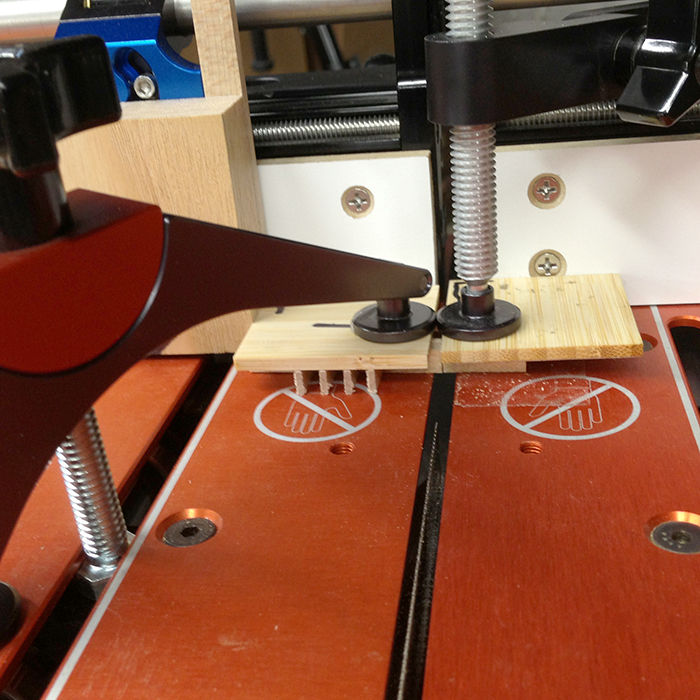
Here’s what it looks like on the JMP…
The complete clamping set-up on the JMP. On the falloff side of the saw, there is double stick tape on the table and on the underside of the clamp pad. This keeps these thin pieces of wood from bending during the cut. There is too much work in each of these to lose them at this step.
You can see how well the tape holds here…
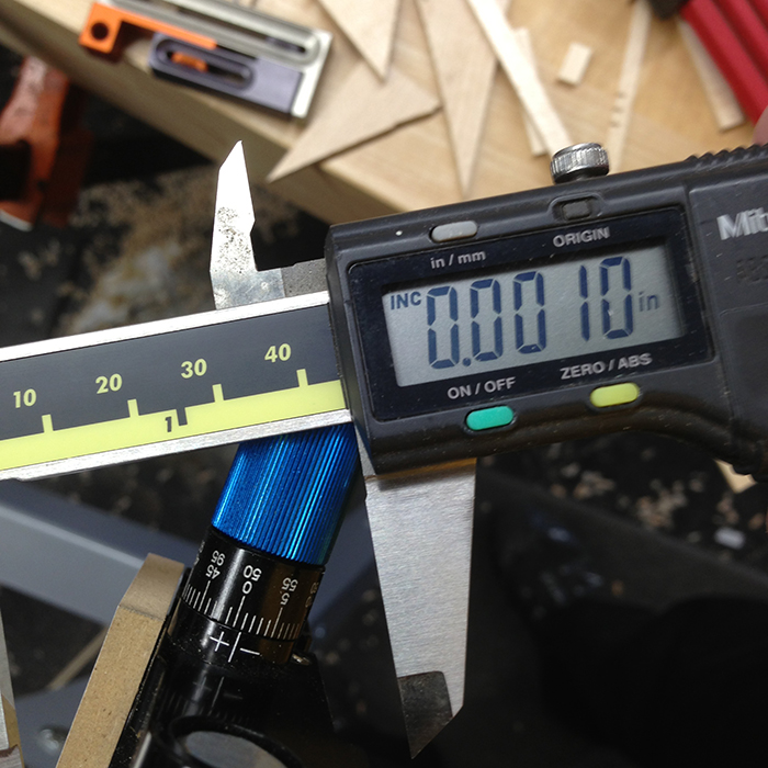
Hand fitting these was a breeze. The very first thing I did was add a wood block to one of the Precision Fence fingers for a larger reference surface (you can see it in the pic above). I then set the stop up to cut 1.750″ and set the dial on the fence to ‘0″. Next, I opened my digital calipers to 1.750″ and then “zeroed” the caliper. This means when the caliper was closed it read -1.750″. Last, I measured the width of an opening and the caliper read 0.001″. Now all I needed to do was set the dial on the fence to +0.001″. It was that easy. Here is a pic of the caliper and the dial…
Here is a finished cut grid…
Each grid in the board needed a stop for the lattice. These were measured and cut using the technique above and glued in place. I used a double square with the blade protruding .2200″ for flushing the tops of the lattice with the top of the “bones” which defined the board.
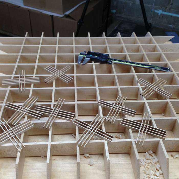
Here the grid is ready to be seated. They are retained with a tiny amount of glue on each end of the four anchor sticks. Each grid required a gentle tap home. The butt joints, all at odd angles, are light tight.
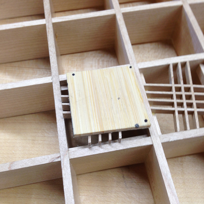
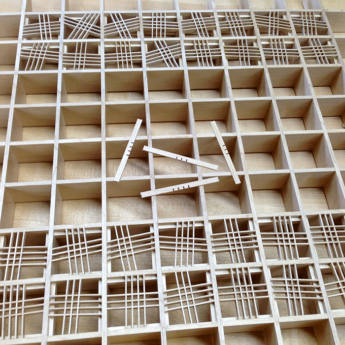
This was tense because I had almost no room for error, which was an error in itself. Here are all the remaining pieces after final assembly.
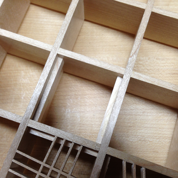
The top was hand sanded with a sanding block and finished with wax. Here is the almost finished board…
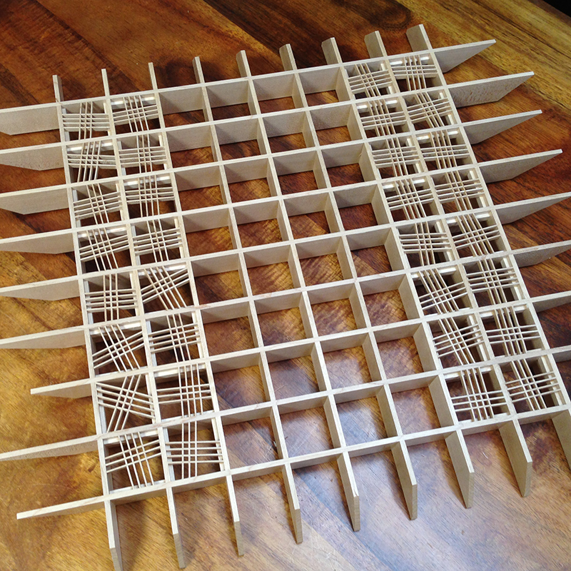
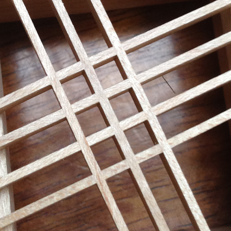
Here’s a close up of the cross lap joints, they are almost invisible…
This aspect of the project took 7 board feet of eastern hard rock maple and 47 hours. It was really fun because I didn’t screw up (thank goodness). The last thing I am going to do is put hidden feet on the board and elevate it about .375″, this creates some really cool shadows on whatever it rests on.
I hope this helps. You can use these techniques to make lots of interesting grids, I have another half dozen or so ideas from making this thing and oh so little time…
John
Fog of War Board
John,
Wicked cool! Great way to make sure the angles will fit the grid perfectly. I don’t see it in the pictures, but for the first two cuts that would have sticks hanging out to interfere with the fence and stop block, how did you make those cuts?
Thanks,
Rutager
Rutager-
The first time I made these I had a false fence system clamped to the JMP top. On this version, because I did not have many spare parts, I took the first two sides down on a stationary disk sander. I also neglected to mention that when cutting the small grids I switched over to the 32 TPI blade. Huge benefit and really efficient.
-John
John,
Very nice and damn instructive. Thanks for this.
You are welcome! The JMP can do amazing things once you realize work holding is the name of the game.
-John
John,
Putting the stick grid on a base that is the same size as the space between the base grid is as simple as it is brillant, no matter where the sticks come out, they end up at the perfect angle to the grid walls; I could see making a “V” cut in a base plate could allow for cutting all four sides even with the sticks hanging out.
The chess board is impressive; I remember seeing it on the first day of class and wanting to make it even more than the pieces! Although making the pieces pushed my JMP skills upward several notches.
-Rutager
Thanks for this, John. A very impressive photo essay of incredibly precise joinery. I love your solutions to the various problems you encountered (or anticipated). But that’s a big part of the fun of woodworking, isn’t it? I lie awake at night, coming up with solutions to interesting cuts, the order of operations, the tools I’ll use, or nonlinear ways of approaching a problem. Woodworking becomes a very pleasant extension of my science, which fundamentally is really not that different in the application of creativity and synthesis of tools, knowledge and approaches.
As for using skids to get properly-thicknessed pieces, I wait in breathless anticipation for my CT-18! I have a growing list of projects that will benefit from those depth skids!
Thank you so much for sharing your amazing knowledge and creativity with us. Those poor non-DSN members just don’t know what they’re missing!
— Peter
I wish I had the CT-18 for this job! I used wood skids attached via DS tape for the board bones.
I think I should write something on how to REALLY use digital calipers as I believe most folks under utilize the potential. Now to find the time…
BTW, there is light at the end of the CT-18 tunnel!
-John
Rutager,
Those pads were not exactly the opening size, but close. I wanted to see the cuts as they occurred and not score the pad as well. FYI.
John
John,
I hadn’t heard of gage pins before this and went looking on the web at them. I see they come in sets of plus and minus. What the difference and why use one over the other?
Thanks
P
Paul,
A very common use for precision gage pins is for measuring hole diameters, and as such the minus set provides about 0.0002″ clearance. The same can be said for the plus set. So, if you have a hole with a plus or minus tolerance spec, you can quantify with both sets.
Now this is going to sound strange coming from me, but in woodworking, buy the least expensive gage pins you can find. I own pins gages from .001″ thru .750″ by 0.001″ increments and spent less than $150. These very pins would get me fired in an aerospace machine shop, but my work doesn’t leave the ground.
They are indispensable for; holes, grooves, spacers, and measuring all sorts of gaps. I really like them for setting the depth skid “gap” on my planes. You set the plane up to cut silky shavings, set your skids to make a test cut, cut until the plane quits cutting and measure. You will be off your intent most likely, but now you know what pins to use. BTW, the pins will vary by 0.001″ at the nose and rear of the sole but it will not matter.
Does this help?
John
Yep..
Thanks
Bogles the mind we humans can make machines that make other things of such precision. We’re a fascinating species.
Ironically, gage pins are rather crude compared to other methods. That makes us even more interesting as a species.
John,
I am wondering if you needed to pay attention to the grain orientation when thicknessing the lattice strips. It seems to me that if the grain were
oriented in the “bad” direction that causes tear out, the blade of the plane would tend to pull the strip up towards the bottom surface of the plane, resulting in the piece being planed too thin. It seems like it could end up quite thin with repeated passes that catch the badly oriented
grain.
Don-
Grain direction absolutely matters, but it is not a big deal. The stock was about 0.010″ oversize and my plane was set up to take about 0.0015″ passes. You KNOW on the first pass if the stick is backward. rotate it, clean up the “bad” pass, flip 180 degrees and plane away until the skids hit.
-John
John,
Digital calipers and gauge pins; tools that aren’t normally associated with wood working, do you have any more that you would recommend for our shops?
Thanks,
Rutager
Rutager,
The obvious answer includes BCTW tools. That was easy.
-John
John,
If you can’t get this tool making gig to pay off, any thoughts about getting the contract to make stir sticks for Starbucks?
-Rutager
Rutager-
Get back to work!
-John
“Rutager get back to work,” is what you’ll be yelling if you make the mistake of hiring me at your stir stick factory- on the plus side, I do have my own tools.
John,
In the picture of the planing board, I can’t tell, but is that a melamine board with a groove in it or some other thin material applied to a board?
Thanks,
Rutager
Gentlemen, Rutager, Dennis,
For those of you that care, please stay tuned. For those of you that do not either ignore this completely or turn your radio down. I will be coming to the BCTW 30th Gala. Arriving Wednesday and leaving Sunday. 😮 I am sorry to inflict myself upon you all but really, how could I miss this?
You may now turn your radio back on or up. 😮
Fred
Fred-
That’s good news! Please leave your Entertainment Center in PA…. it would fit right in out here in Birkenstock Country.
-John
John,
I am sorry but the EC has already been shipped and will arrive at BCTW next week. Oh, and I have hired a marching band to coincide with it’s arrival. 😮
Fred
John: I am good and properly jealous of the people going. Best of luck on the exhibit!
I’m making up my mind on WIA in November and noted BCTW isn’t (yet?) listed as an exhibitor. While my hands would probably be safer, you’d certainly be missed.
Dave
John,
For the thicknessing jig, did you just cut a groove in some melamine or did you stick some melamine on top of a board to create the groove? And is there DS tape stopping the pieces being planed from moving? Thanks.
Kevin
Kevin,
I just cut a groove in the melamine. To keep the parts from moving I super glued a small stop, it will get planed to thickness on the first piece and is net thereafter.
John
John,
Is planing the sticks to thickness with the HP-8 more accurate than cutting them with the JMP? (asks the guy without either at the moment…)
Thanks,
d.
Daniel;
This is an apple vs oranges question.
The JMP is limited in the ability to rip cut, but it’s ability to crosscut to crazy tolerances is excellent. I can repeatedly cross-cut to lengths that vary only by a few thousandths of an inch.
When I built the Fog of War, I used the HP-8 and the thickness of all those little sticks did not vary by more than two thousandths of an inch. That is incredible, and basically this is machinist tolerances with a hand tool.
I hope this helps.
-John
John,
Yes, it does. I’ll order an HP-8 when it comes back around. If one happens to be lying around let me know. 🙂
d.
I’m guessing the overall length and width of the base is about 21″? It looks like you made the lengths of the angled ends vary a bit – conveying more chaos?
Kevin,
The metaphor of the board gives the participants two choices, one is safe and predictable and the other (the sharp side) a visual, deliberate warning.
The internal size of the squares is 1.75″ x 1.75″. The board is not totally square due to the staggered sharp components but it is roughly 25″ square.
-John
Thanks! I think I’ll give it a shot building it this winter.
Cheers
Kevin